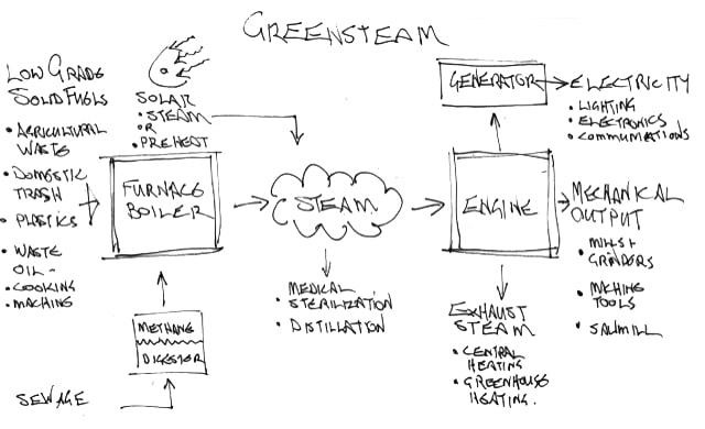
Greensteam
developing conceptual engine designs
The Greensteam research project aims to develop a sustainable alternative to internal combustion generators for small-scale power generation in remote communities. As the Engine Team Lead, I was responsible for mentoring 3 students, conducting research and design relating to power generation from steam, and writing research reports and grant proposals.
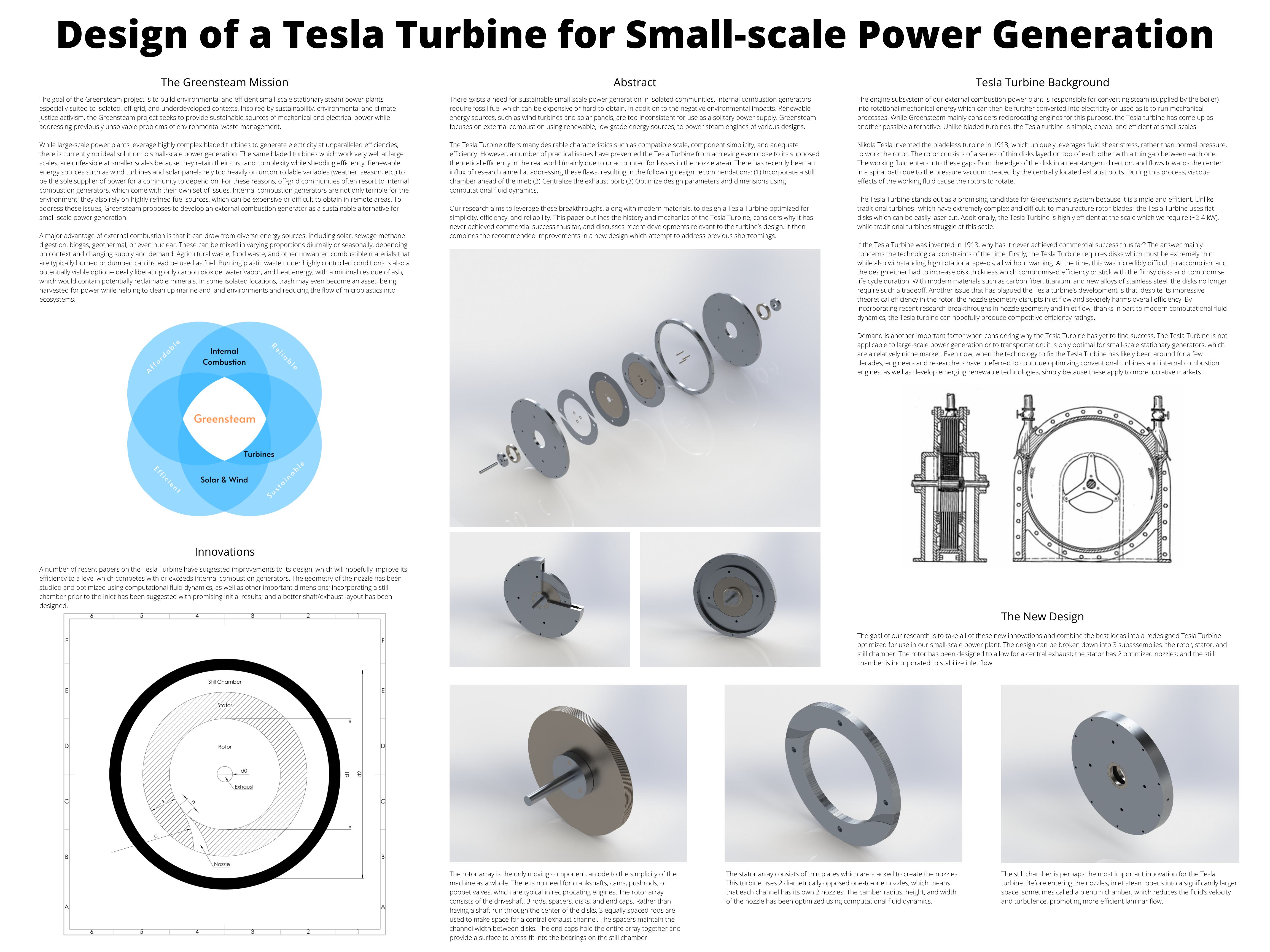
Tesla Turbine
I investigated the potential of a bladeless Tesla-style turbine for this application, presenting my work at the 2021 UCI Undergraduate Research Symposium.
Reciprocating Engines
I studied a variety of reciprocating engine designs, optimizing for simplicity and repairability in line with the project’s goals.
Cam-actuated Uniflow Boxer Engine
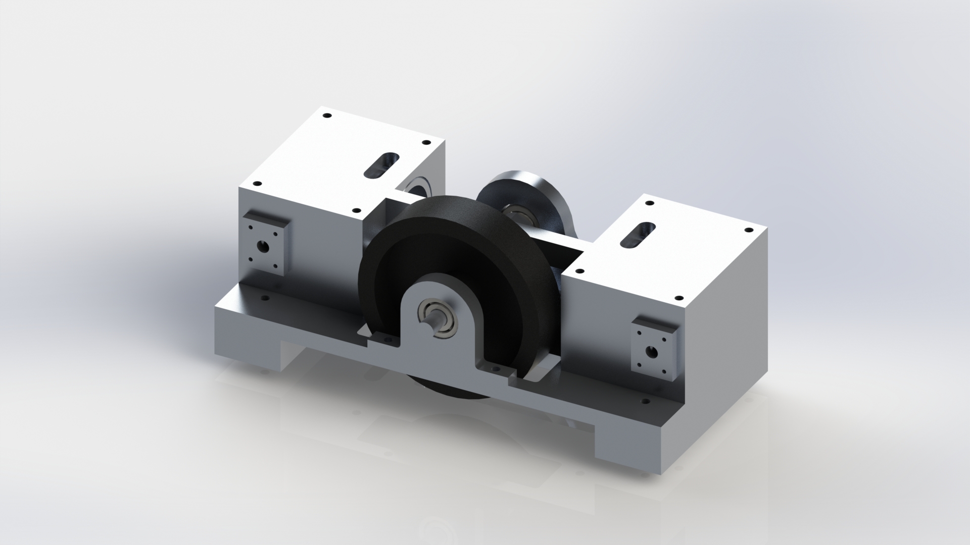
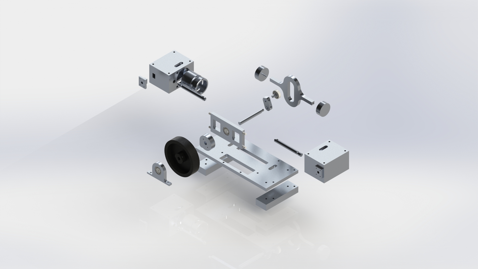
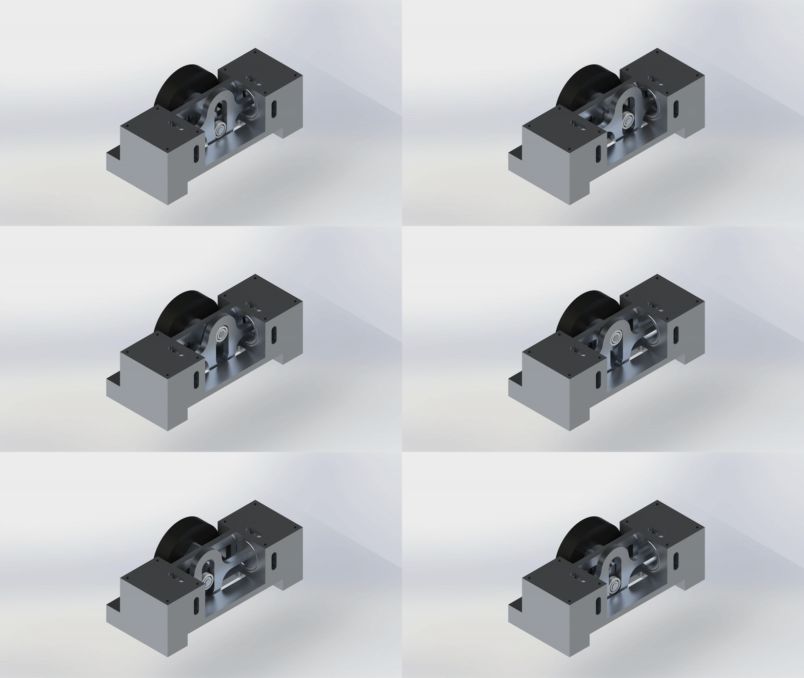
This engine has two diametrically opposed cylinders with corresponding pistons that are connected by a scotch yoke. Since it utilizes uniflow exhaust and the cylinders are opposite each other, one cylinder is always in a power stroke while the other is in its return stroke. A flywheel is necessary to ensure smooth running at top and bottom dead center. An overhung crank has been implemented in the design to drive the scotch yoke. Inlet valve actuation is accomplished by 2 spool valves driven by a cam attached to the shaft.
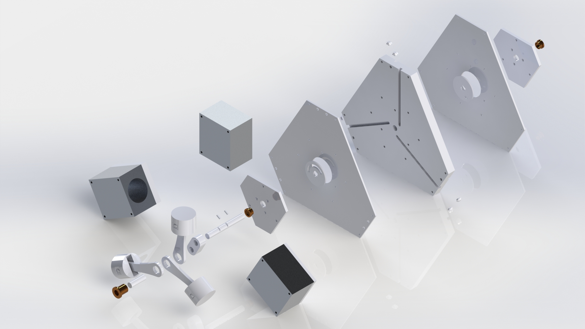
Disk-actuated Triradial Engine
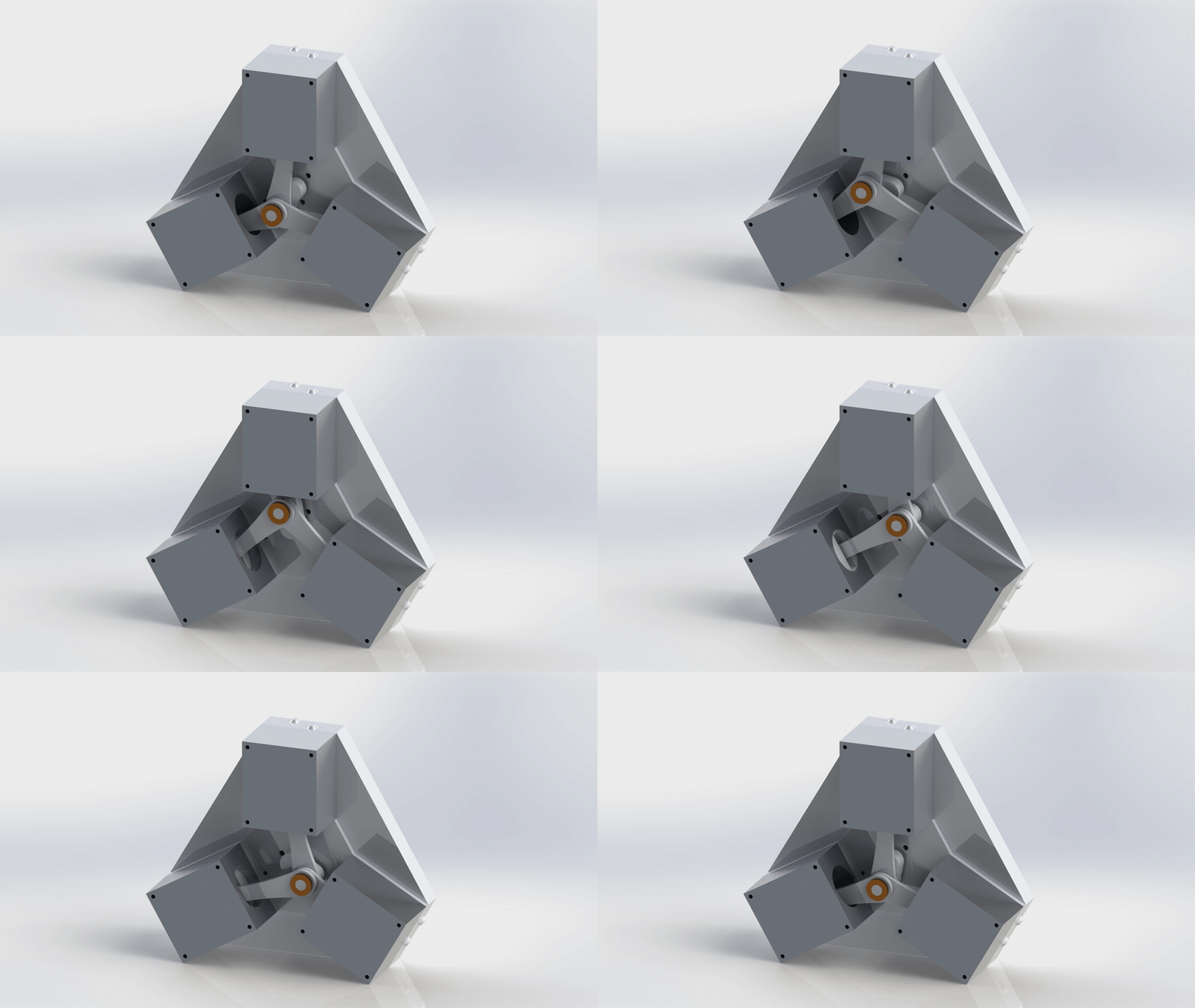
This engine has a triradial layout meaning the 3 cylinders are spaced equally around the shaft. Each cylinder is offset slightly from the others so the piston rods may all attach to the same overhung crank. Behind the cylinders, the shaft drives 2 thin disks, on each side of the main plate, which act as the exhaust and inlet valves. Each disk has a slot–the shape of which determines timing and flow rate–which allows exhaust to escape to the atmosphere and inlet steam to enter the cylinders, both through milled manifolds in the main plate. The 2 disks do the same work as 6 traditional poppet-type valves, vastly reducing the number of moving parts, and the triradial layout removes the need for a flywheel.
Double-acting Uniflow Compound Engine
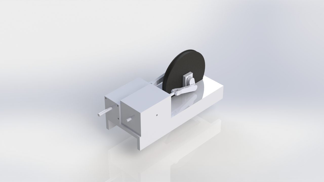
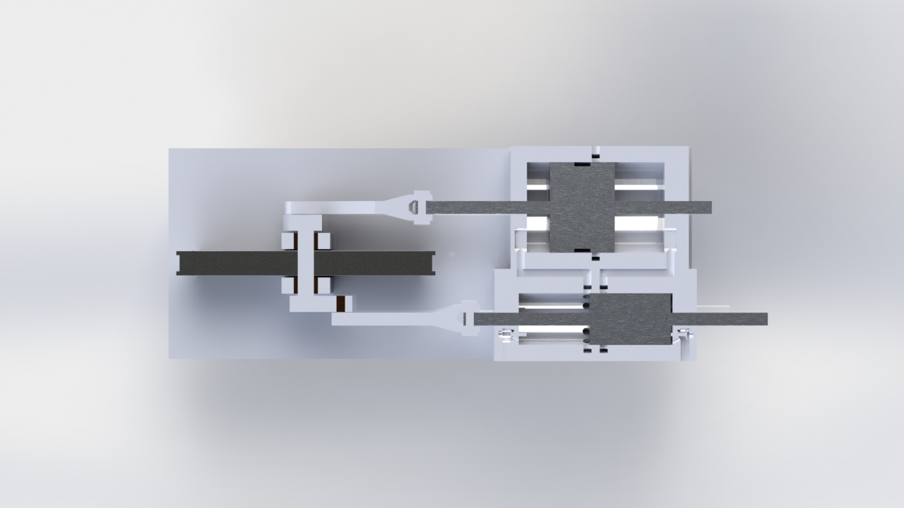
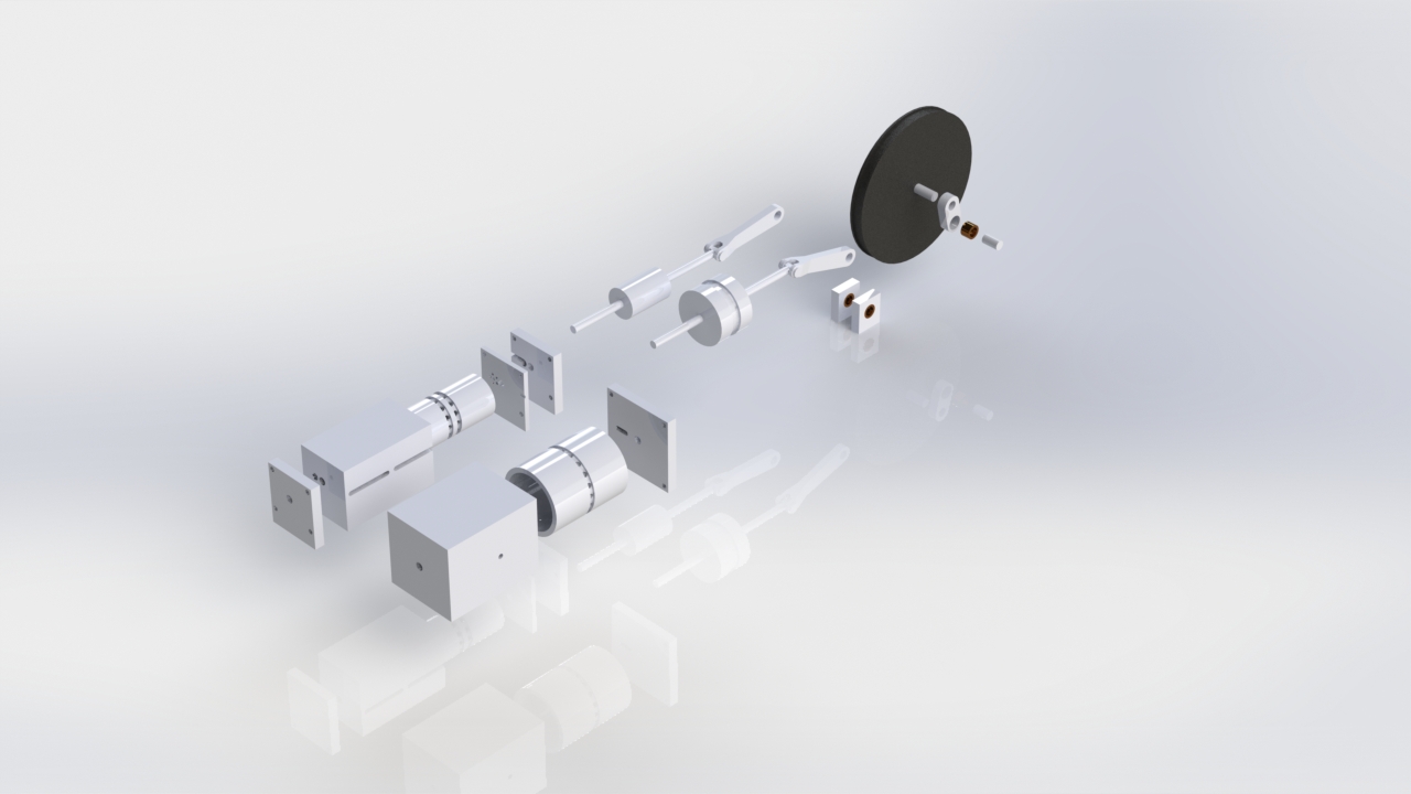
This 2 stage double-acting inline compound engine replaces the traditional cross-slide by extending the piston rod through the back end of the cylinder, thereby supporting the piston on either end. Steam enters the high pressure cylinder on both ends through bash valves. After high pressure expansion, steam exits through uniflow ports into a manifold which goes to the low pressure cylinder. Here, the semi-expanded steam expands again before finally exiting through uniflow exhaust ports into the atmosphere. The timing between high and low pressure pistons is slightly offset such that for the first ~5% of low pressure power stroke, the low pressure piston acts as a pump to improve the exhaust performance of the high pressure cylinder.
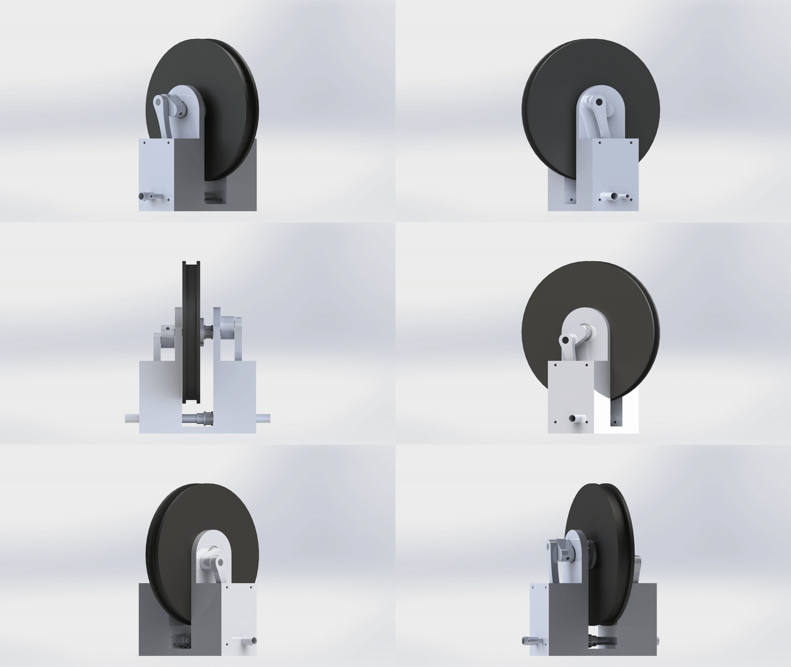
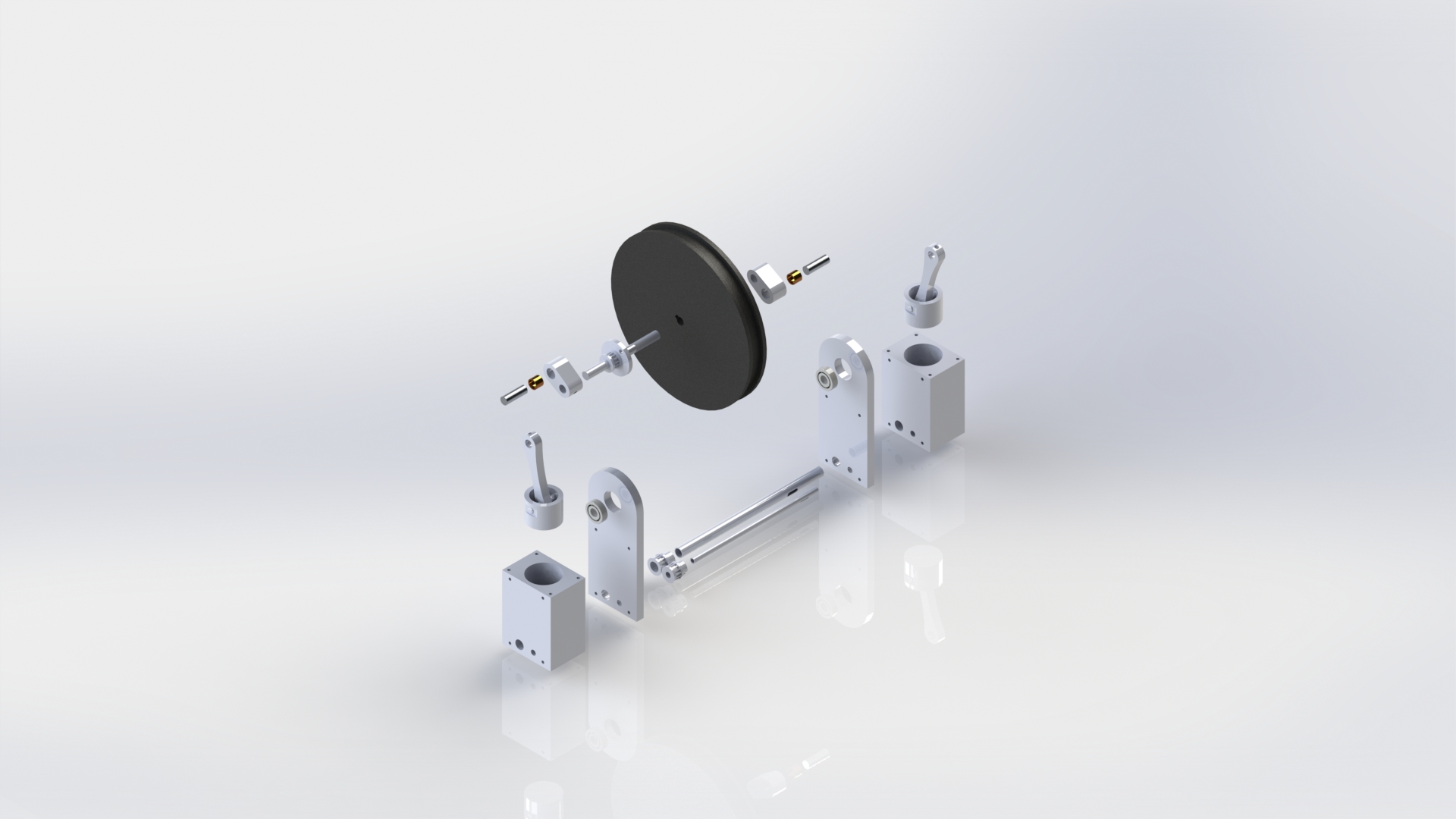
Tube-actuated Dual-Inline Engine
This engine has 2 cylinders, one on either side of a central flywheel. Overhung cranks drive the cylinders, diametrically opposed so that while one piston is in power stroke the other is in return stroke. This layout is akin to that of a bicycle, where the 2 pistons are the cyclist’s legs which force the pedals (overhung cranks) to rotate. Since there are 2 overhung cranks, no side of the shaft is free to act as the output driveshaft, so the flywheel also acts as a pulley which links with an external driveshaft. There are 2 rotating hollow pipes that run below the head of the cylinders, parallel to the crankshaft, and act as the inlet and exhaust valves. These pipes are linked to the crankshaft via a timing belt. The inlet tube is fed a constant supply of steam from one side and sealed on the other, while the exhaust tube is open on both sides to atmospheric pressure. Both pipes each have 2 slotted cuts that open into the cylinders for a period which determines timing for inlet, expansion, exhaust, and compression.
Tube-actuated 3 cylinder Inline Engine
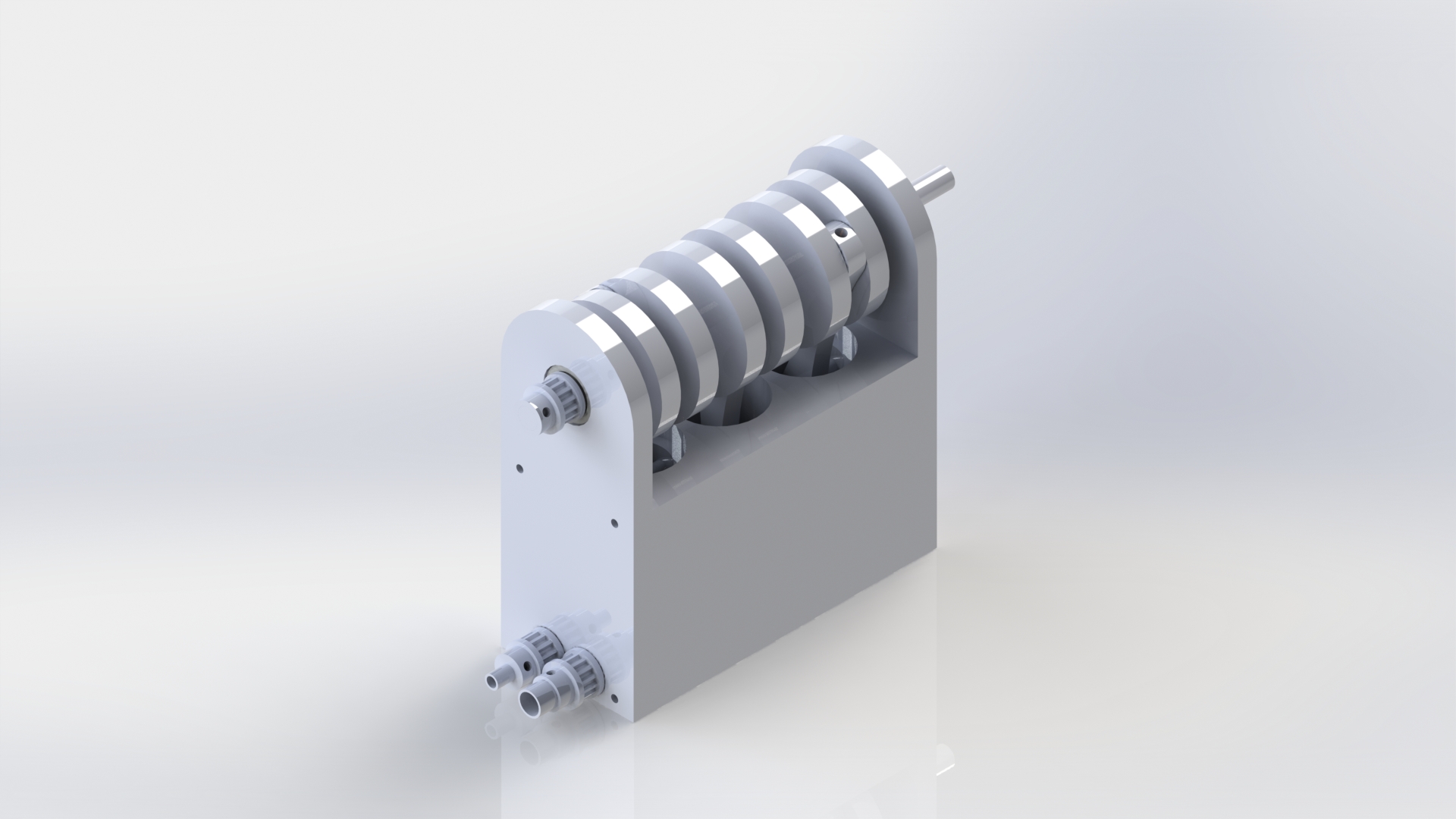
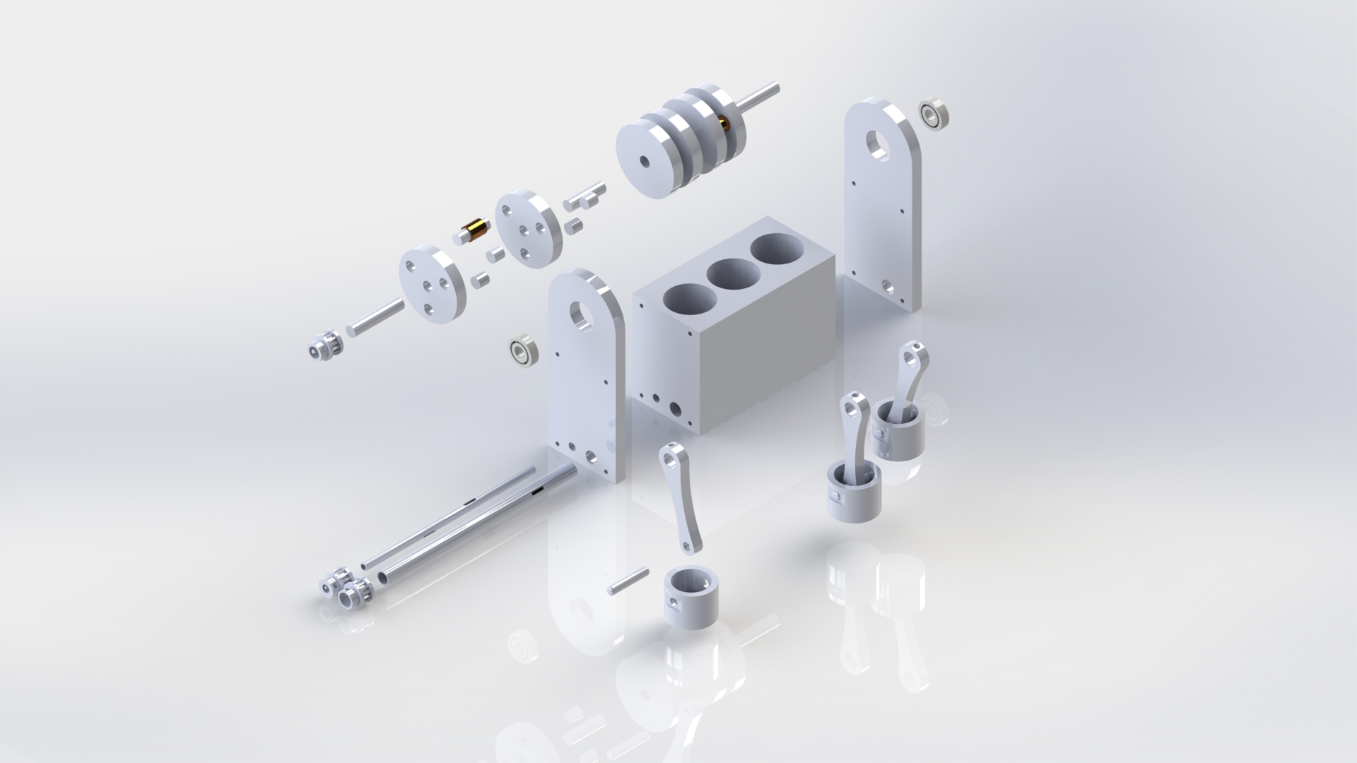
This engine has 3 inline cylinders bored out of a single block. Due to this layout no flywheel is required. There are 2 rotating hollow pipes that run below the head of the cylinders, parallel to the crankshaft, and act as the inlet and exhaust valves. These pipes are linked to the crankshaft via a timing belt. The inlet tube is fed a constant supply of steam from one side and sealed on the other, while the exhaust tube is open on both sides to atmospheric pressure. Both pipes each have 3 slotted cuts that open into the cylinders for a period which determines timing for inlet, expansion, exhaust, and compression. The benefit of this valve system is that the 2 pipes essentially replace the need for 6 valves, reducing the number of moving parts while maintaining perfect control over valve timing.
